Typ Engineering Drawing
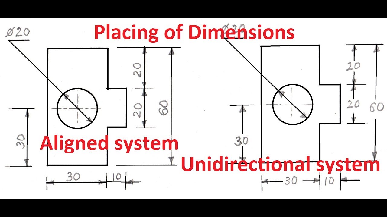
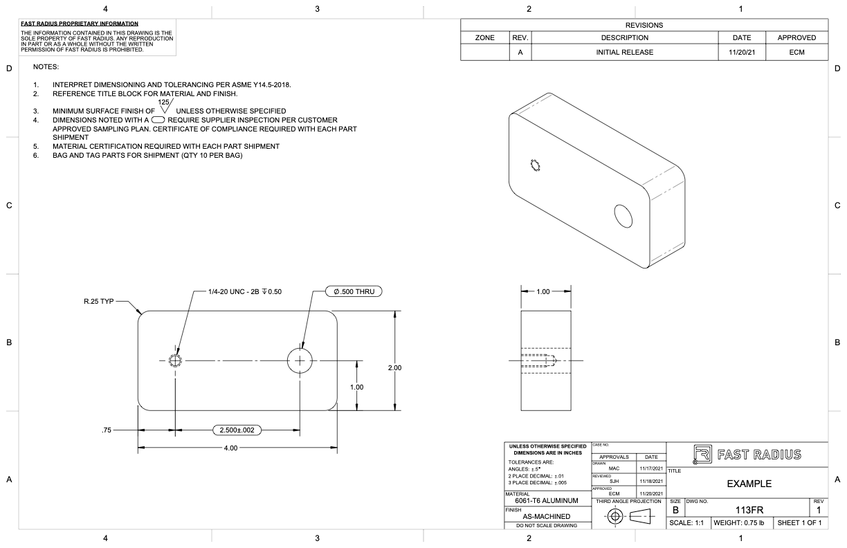
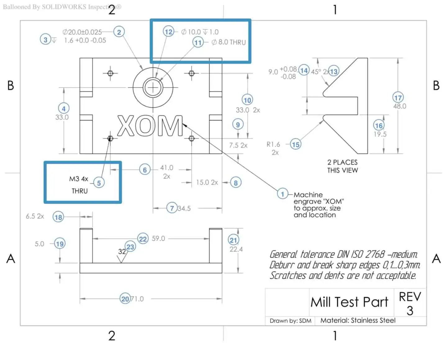
Typ Engineering Drawing - Opens in new tab or window. Because there is no large space on a drawing to contain all the text to illustrate the image, abbreviations, and symbols are often used in engineering drawings to communicate the characteristics of the product to be manufactured. Instead of detailing the same feature multiple times, the designer can use “typ” to signal that it is a standard or recurring component. This list includes abbreviations common to the vocabulary of people who work with engineering drawings in the manufacture and inspection of parts and assemblies. A typical dimension callout will occasionally be followed by a 2x, 5x or similar, to specify the quantity of features which are tolerance the same. If the isometric drawing can show all details and all dimensions on one drawing, it is ideal. I know that this particular length is not critical to the function of the entire part, so is this just a suggested dimension length”? Web typical on an engineering drawing identifies a repeated feature. A complete understanding of the object should be possible from the drawing. Web engineering drawing abbreviations and symbols are used to communicate and detail the characteristics of an engineering drawing. If the isometric drawing can show all details and all dimensions on one drawing, it is ideal. This standard defines the types of engineering drawings most frequently used to establish engineering requirements. For example, to design in a radius of r.250 on. This helps avoid any ambiguity or uncertainty. Web to save space on blueprint drawings, architects and builders use abbreviations and acronyms. These notes communicate certain expectations, definitions, or standards for the entire project. Jason siegel, who grew up in philadelphia. I know that this particular length is not critical to the function of the entire part, so is this just a suggested dimension length”? For example, if the drawing shows 8 holes on a bolt circle, and just one is dimensioned, with typ or (typ) following the dimension label, it means that that hole is typical of all 8 holes; Join your peers on the internet's largest technical engineering professional community. The drafter shall provide additional information to completely identify all applicable joints. A typical dimension callout will occasionally be followed by a 2x, 5x or similar, to specify the quantity of features which are tolerance the same. Web the duplication of identical welding symbols on a drawing may be avoided by designating a single welding symbol as “typical” (abbreviated as. Web typical on an engineering drawing identifies a repeated feature. “stamped plans” are plans bearing the seal of a registered engineer or architect. Have an abbreviation we haven't listed?add your knowledge to our. Drawings for specialized engineering disciplines (e.g., marine, civil, construction, optics, etc.) are not included in this standard. Jason siegel, who grew up in philadelphia. The exception is that typ is an accepted standard for multiple identical weld symbols; Web engineering drawing abbreviations and symbols are used to communicate and detail the characteristics of an engineering drawing. “stamped plans” are plans bearing the seal of a registered engineer or architect. So once a manufacturing engineer gets the drawing, he can start the production process without. For example, if the drawing shows 8 holes on a bolt circle, and just one is dimensioned, with typ or (typ) following the dimension label, it means that that hole is typical of all 8 holes; Because there is no large space on a drawing to contain all the text to illustrate the image, abbreviations, and symbols are often used. Web typ means 'other features share the same characteristic. So once a manufacturing engineer gets the drawing, he can start the production process without a. In other words, it means that the other 7 holes are that size also.' These notes communicate certain expectations, definitions, or standards for the entire project. This standard defines the types of engineering drawings most. Instead of detailing the same feature multiple times, the designer can use “typ” to signal that it is a standard or recurring component. The exception is that typ is an accepted standard for multiple identical weld symbols; Web the purpose of engineering drawings. “stamped plans” are plans bearing the seal of a registered engineer or architect. Web any engineering drawing. Web engineering drawing abbreviations and symbols are used to communicate and detail the characteristics of an engineering drawing. Web typ and ref.dimension definition on drawings. It describes typical applications and minimum content requirements. This helps avoid any ambiguity or uncertainty. Web typical on an engineering drawing identifies a repeated feature. Web the duplication of identical welding symbols on a drawing may be avoided by designating a single welding symbol as “typical” (abbreviated as “typ”) and pointing the arrow to the representative joint. Have an abbreviation we haven't listed?add your knowledge to our. Learn the standard shorthand in this guide. I know that this particular length is not critical to the. “stamped plans” are plans bearing the seal of a registered engineer or architect. Web the gsfc engineering drawing standards manual is the official source for the requirements and interpretations to be used in the development and presentation of engineering drawings and related documentation for the gsfc. Because there is no large space on a drawing to contain all the text. Instead of detailing the same feature multiple times, the designer can use “typ” to signal that it is a standard or recurring component. 100 series ls control panel and details cover index drawings (zip, 3mb) 200 series ls triplex less than 25hp 208 480v pump panel (zip, 32mb) It describes typical applications and minimum content requirements. Web engineering documents can. Web the purpose of engineering drawings. And after earning a degree in welding and materials engineering, he spent the next 10. This helps avoid any ambiguity or uncertainty. Web engineering documents can be hand signed with a pen, dated, and sealed by the professional engineer in responsible charge. “stamped plans” are plans bearing the seal of a registered engineer or architect. Because there is no large space on a drawing to contain all the text to illustrate the image, abbreviations, and symbols are often used in engineering drawings to communicate the characteristics of the product to be manufactured. Web the duplication of identical welding symbols on a drawing may be avoided by designating a single welding symbol as “typical” (abbreviated as “typ”) and pointing the arrow to the representative joint. Drawings for specialized engineering disciplines (e.g., marine, civil, construction, optics, etc.) are not included in this standard. Web i have a drawing for an assembly and one of the dimensions on the drawing is for a length that has typ next to it. This standard defines the types of engineering drawings most frequently used to establish engineering requirements. Web an engineering drawing is a type of technical drawing that is used to convey information about an object. The signature may not be a scanned, facsimile, digitally created, or copied image. One can pack a great deal of information into an isometric drawing. The mechanical engineering branch, mechanical systems division, has been delegated So once a manufacturing engineer gets the drawing, he can start the production process without a. Instead of detailing the same feature multiple times, the designer can use “typ” to signal that it is a standard or recurring component.
3 Types Of Engineering Drawings Printable Templates Free

Engineering drawing symbols TYP שרטוט סימון אוביקט טיפוסי YouTube
Engineering Drawing Symbols And Their Meanings Pdf at PaintingValley
Engineering Drawing Symbols And Their Meanings Pdf at GetDrawings
What to Include in Your Engineering Drawing Fast Radius

6 types of engineering drawings

What is TYP in Engineering Drawing. Engineering Drawing me TYP ka kya

a. Typical engineering drawing with dimensioning lines and text, and b
How To Prepare A Perfect Technical Drawing Xometry Europe
Types Of Dimensions In Engineering Drawing at GetDrawings Free download
Record Documents Digital Upload Via Box;
For Example, To Design In A Radius Of R.250 On.
Learn The Standard Shorthand In This Guide.
Web In Florida, Currently, Most Construction Projects Require Stamped Drawings To Obtain The Building Permit.
Related Post: