Engineering Drawing Symbols And Meanings
Engineering Drawing Symbols And Meanings - The following are commonly used engineering drawing symbols and design elements. This document describes and illustrates common dimensioning, gd&t, architectural, piping, and electrical symbols. However, symbols can be meaningful only if they are created according to the relevant standards or conventions. Web a convenient guide for geometric dimensioning and tolerancing (gd&t) symbols at your fingertips. Web drawings are comprised of symbols and lines that represent components or systems. We offer you our tips which we believe are useful for dispelling uncertainty by comparing the symbol with its graphic representation. Web understanding the symbols used on engineering drawings in welding, piping, electronics, and the fluid power industry. Web for example, engineering symbols are used in technical drawings to convey the specific geometry and other details about pieces of equipment or components. Web engineering drawing abbreviations and symbols in addition to traditional topics, it contains information on geometric dimensioning and tolerancing, design process and design for manufacturability, and the basics of descriptive geometry. Web engineering drawings (also known as blueprints, prints, drawings, or mechanical drawings) are detailed outlines that represent the information and requirements required to build a certain item or product. Web find common gd&t symbols in convenient charts broken down by their use in drawing and drafting. Current industry drawings are used in illustration. Web for example, engineering symbols are used in technical drawings to convey the specific geometry and other details about pieces of equipment or components. The following are commonly used engineering drawing symbols and design elements. However, engineering drawings are complex. Web cnc design is an integral part of cad/cam technology. To limit errors caused by personal interpretation, engineering drawings and diagrams are governed by standardized language and symbols. They are full of symbols, abbreviations, and strange phrases that you may not be able to decipher. However, symbols can be meaningful only if they are created according to the relevant standards or conventions. Web drafting symbols symbols provide a “common language” for drafters all over the world. It is more than a drawing; You can also check out the gd&t symbols and terms on our site. This document describes and illustrates common dimensioning, gd&t, architectural, piping, and electrical symbols. Web engineering drawing abbreviations and symbols are used to communicate and detail the characteristics of an engineering drawing. Web the following are definitions commonly used throughout industry when. Web cnc design is an integral part of cad/cam technology. Web in this post, we'll go over the basics of how to read engineering drawing symbols, including p&ids and pfds. You use these drawings for the development and production of a product. You can also check out the gd&t symbols and terms on our site. This is where the meanings. Web it establishes symbols, rules, definitions, requirements, defaults, and recommended practices for stating and interpreting gd&t and related requirements for use on engineering drawings, models defined in digital data files, and in related documents. Web an engineering drawing is a type of technical drawing that is used to convey information about an object. Web basic types of symbols used in. Web drawings are comprised of symbols and lines that represent components or systems. Web basic types of symbols used in engineering drawings are countersink, counterbore, spotface, depth, radius, and diameter. This list includes abbreviations common to the vocabulary of people who work with engineering drawings in the manufacture and inspection of parts and assemblies. Web the following are definitions commonly. Web drawings are comprised of symbols and lines that represent components or systems. This document describes and illustrates common dimensioning, gd&t, architectural, piping, and electrical symbols. The basic symbol types used in engineering drawings are diameter, depth, radius, counterbore, spotface, and countersink. Web an engineering drawing is a type of technical drawing that is used to convey information about an. Using abbreviations and symbols allows for concise representation, making the drawings easier to read and understand. However, symbols can be meaningful only if they are created according to the relevant standards or conventions. Web it establishes symbols, rules, definitions, requirements, defaults, and recommended practices for stating and interpreting gd&t and related requirements for use on engineering drawings, models defined in. Engineering drawings often contain a large amount of information, including dimensions, tolerances, annotations, and other details. Web engineering drawing abbreviations and symbols engineering drawing abbreviations and symbols engineering drawing abbreviations and symbols This list includes abbreviations common to the vocabulary of people who work with engineering drawings in the manufacture and inspection of parts and assemblies. Usually, a number of. A common use is to specify the geometry necessary for the construction of a component and is called a detail drawing. Web in this post, we'll go over the basics of how to read engineering drawing symbols, including p&ids and pfds. Many of the definitions are not official asme, ansi or iso terminology. Click on the links below to learn. Web in engineering drawings, symbols are graphical representations of specific features, instructions, or components. Current industry drawings are used in illustration. It is a graphical language communicating ideas and information. Web engineering drawings (also known as blueprints, prints, drawings, or mechanical drawings) are detailed outlines that represent the information and requirements required to build a certain item or product. Web. Web drafting symbols symbols provide a “common language” for drafters all over the world. It is more than a drawing; They are full of symbols, abbreviations, and strange phrases that you may not be able to decipher. This list includes abbreviations common to the vocabulary of people who work with engineering drawings in the manufacture and inspection of parts and. Click on the links below to learn more about each gd&t symbol or concept, and be sure to download the free wall chart for a quick reference when at. Web engineering drawing abbreviations and symbols are used to communicate and detail the characteristics of an engineering drawing. Web an engineering drawing is a type of technical drawing that is used to convey information about an object. Web start with our guide to blueprints and learn all the basic elements of engineering drawings including symbols, terminology and lots of examples. However, engineering drawings are complex. You use these drawings for the development and production of a product. Web in engineering drawings, symbols are graphical representations of specific features, instructions, or components. Web for example, engineering symbols are used in technical drawings to convey the specific geometry and other details about pieces of equipment or components. You can also check out the gd&t symbols and terms on our site. This list includes abbreviations common to the vocabulary of people who work with engineering drawings in the manufacture and inspection of parts and assemblies. We offer you our tips which we believe are useful for dispelling uncertainty by comparing the symbol with its graphic representation. The basic symbol types used in engineering drawings are diameter, depth, radius, counterbore, spotface, and countersink. Web basic types of symbols used in engineering drawings are countersink, counterbore, spotface, depth, radius, and diameter. It is a graphical language communicating ideas and information. Usually, a number of drawings are necessary to completely specify even a simple component. Current industry drawings are used in illustration.
Mechanical Engineering Drawing Symbols Pdf Free Download at
Engineering Drawing Symbols And Their Meanings Pdf at PaintingValley

Engineering Drawing Symbols And Their Meanings Pdf at PaintingValley

Civil Engineering Drawing Symbols And Their Meanings at PaintingValley
Civil Engineering Drawing Symbols And Their Meanings at PaintingValley

Engineering Drawing Symbols And Their Meanings Pdf at PaintingValley
Engineering Drawing Symbols And Their Meanings Pdf at GetDrawings
Engineering Drawing Symbols And Their Meanings Pdf at PaintingValley
Newest For Civil Engineering Drawing Symbols Chart Pdf Inter Venus
Engineering Drawing Symbols And Their Meanings Pdf at PaintingValley
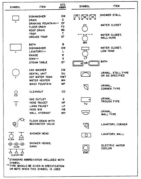
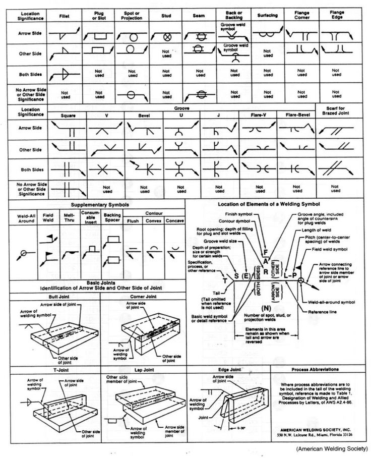
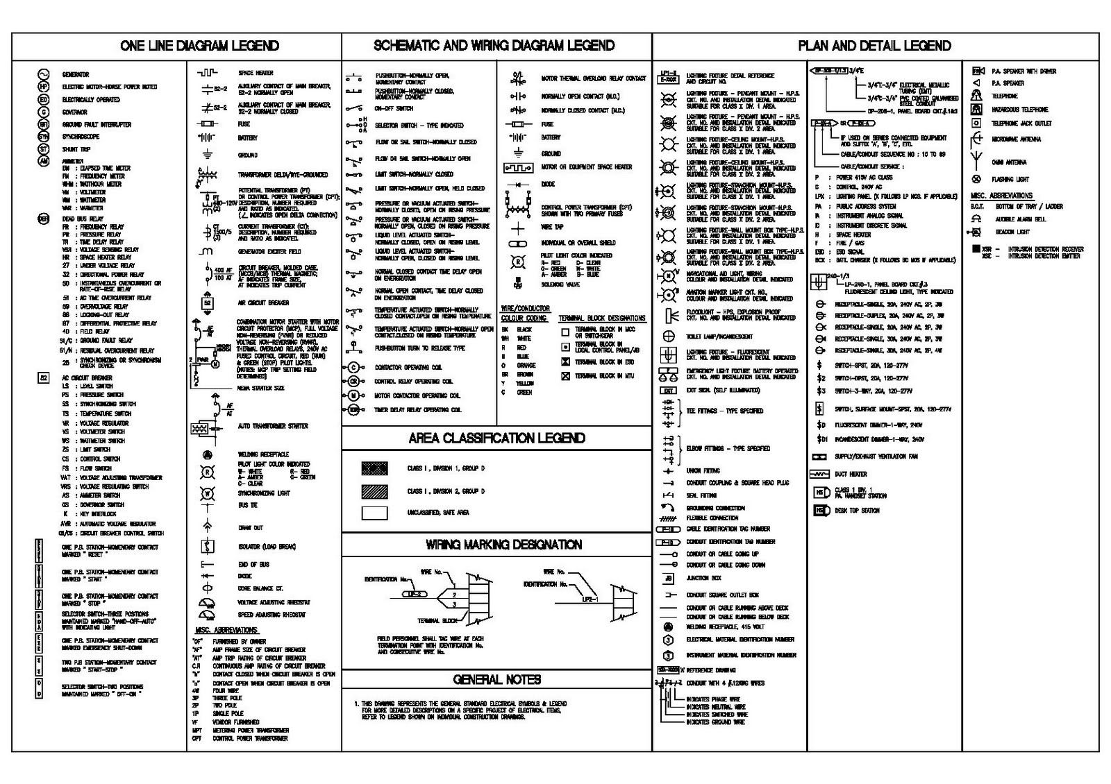
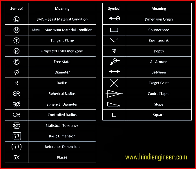
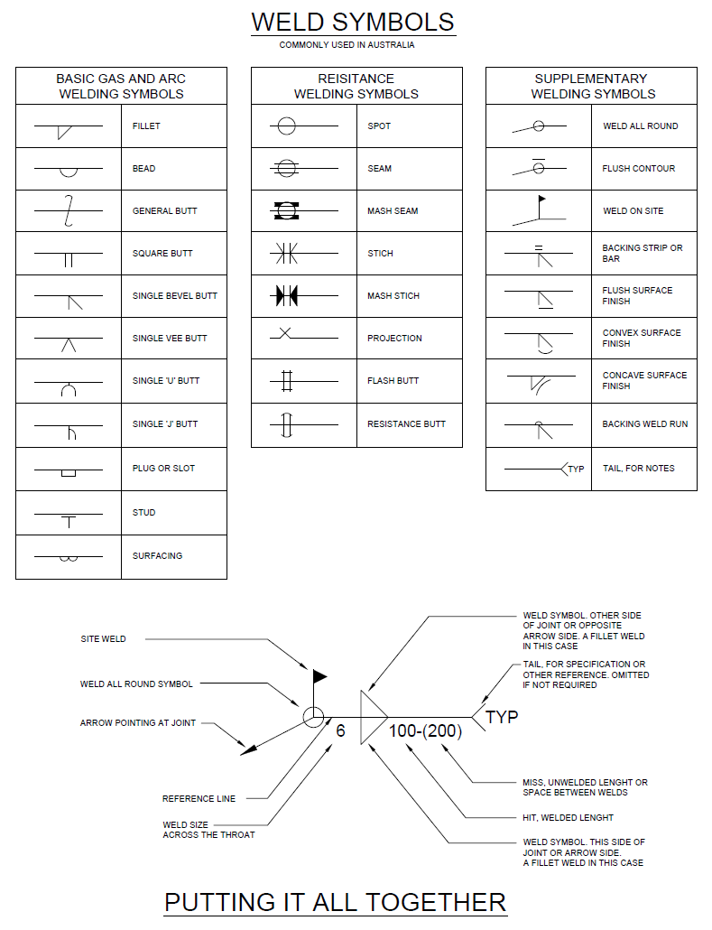
Here Are More Commonly Used Engineering Drawing Symbols And Design Elements As Below.
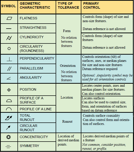
Web A Convenient Guide For Geometric Dimensioning And Tolerancing (Gd&T) Symbols At Your Fingertips.
Engineering Drawings Often Contain A Large Amount Of Information, Including Dimensions, Tolerances, Annotations, And Other Details.
The Following Are Commonly Used Engineering Drawing Symbols And Design Elements.
Related Post: