Engineering Drawing Sample
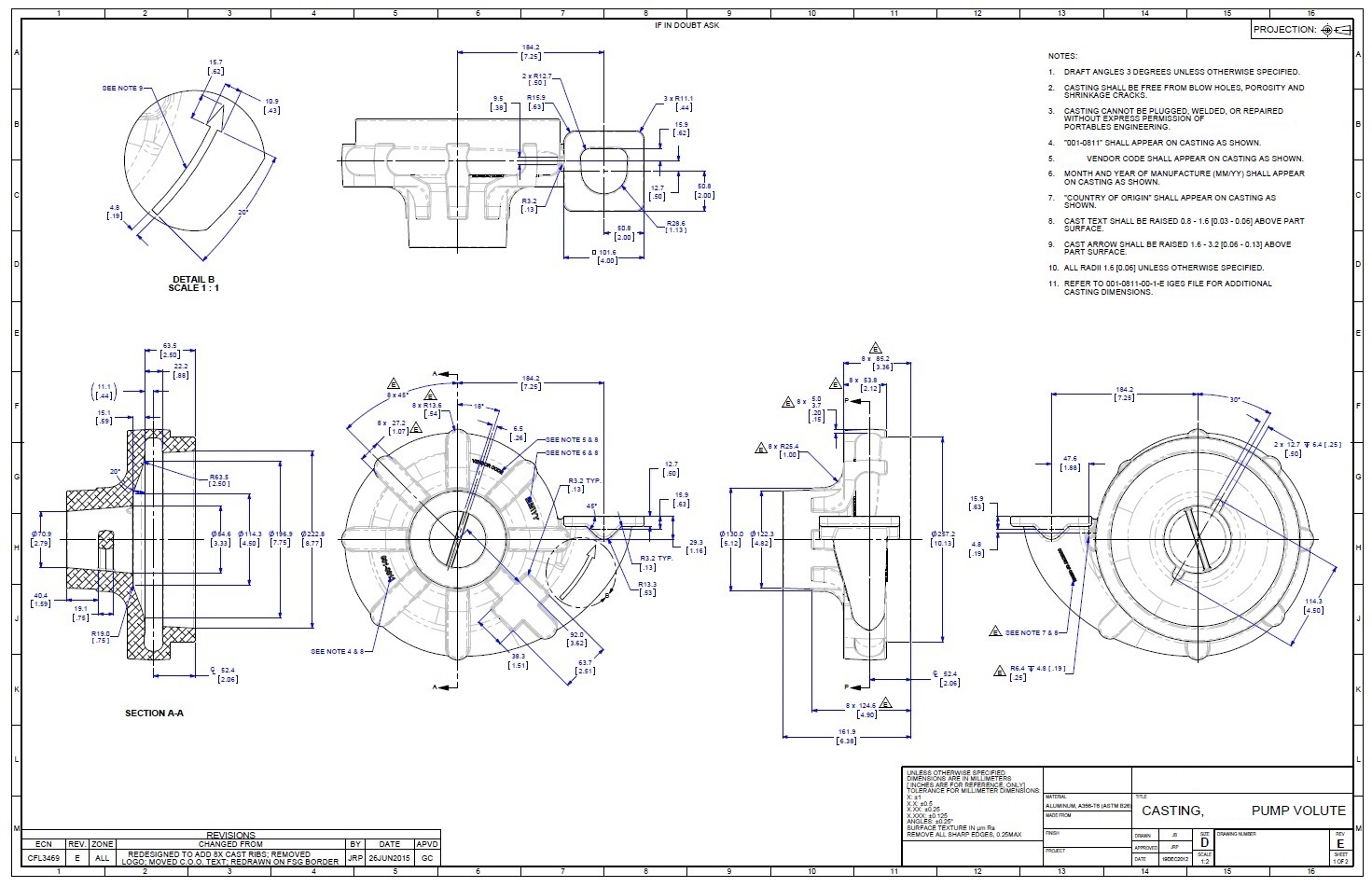
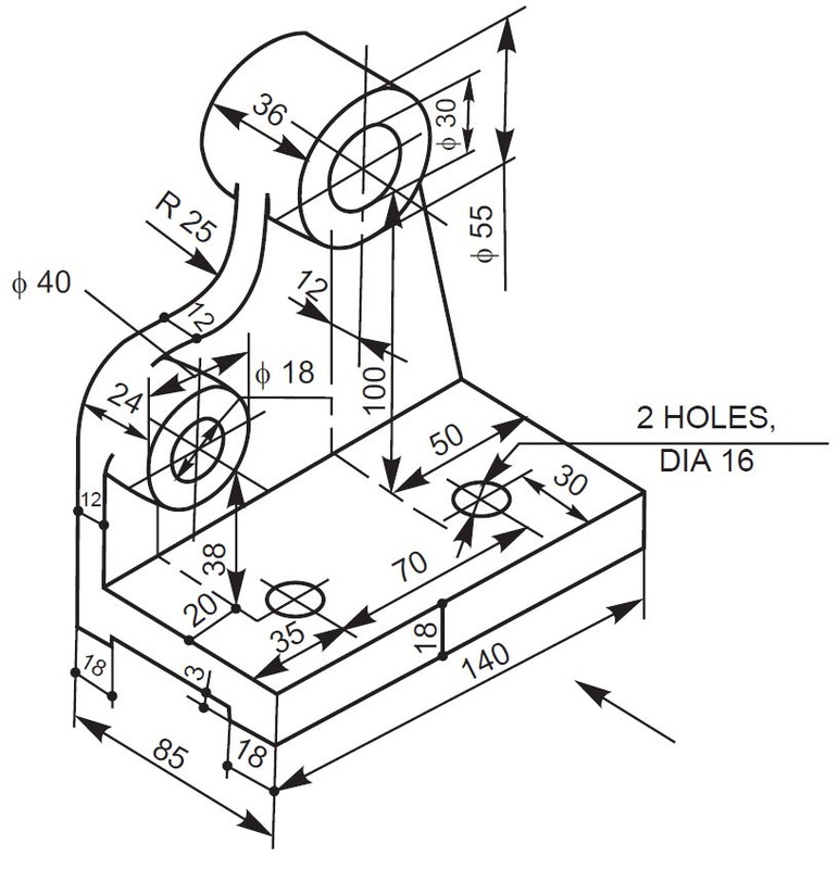
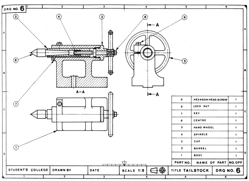
Engineering Drawing Sample - Web engineering drawing standards manual mechanical engineering branch goddard space flight center greenbelt, maryland august 1994 n a t i o n a l i a e r o n a u t i c s a n d s p a c. Engineering drawings are also known as mechanical drawings, manufacturing blueprints and. Through standardized language and symbols,. Web any engineering drawing should show everything: In general, it provides necessary information about the shape, size, surface quality, material, manufacturing process, etc., of the object. Web first, we will consider the sheet sizes, drawing format, title blocks, and other parameters of the drawing form. Web engineering working drawings basics engineering graphics is an effective way of communicating technical ideas and it is an essential tool in engineering design where most of the design process is graphically based. The inside border encloses the. Engineering graphics is used in the design process for visualization,. However, if the object in figure 2 had a hole on the back. Through standardized language and symbols,. The terms used in the table are clarified here: Any engineering drawing should show everything: It is more than simply a drawing, it is a graphical language that communicates ideas and information. Whether you're a student embarking on an engineering career, a hobbyist looking to hone your. Usually, a number of drawings are necessary to completely specify even a simple component. Web the purpose of engineering drawings. If the isometric drawing can show all details and all dimensions on one drawing, it is ideal. One can pack a great deal of information into an isometric drawing. Sheet s5 also shows the footing specification at the timber post, the special requirements for slab step downs at wet areas, how the concrete masonry corners are to be reinforced. Web tips, and theory related to the drawing techniques. This standard defines the types of engineering drawings most frequently used to establish engineering requirements. If the isometric drawing can show all details and all dimensions on one drawing, it is ideal. A complete understanding of the object should be possible from the drawing. An engineering drawing is a technical drawing. It is the graphic language from which a trained person can v isualize objects. Web drawing sheet s5 of our sample engineering drawings provides the exact way we expect the edge beams, internal strip footings and slab thickening to be constructed. Web the main goal of this article is to provide a comprehensive guide to the basics of engineering drawing.. Web download scientific diagram | example of engineering drawing from publication: It describes typical applications and minimum content requirements. There are two major types of drawings namely (i) artistic drawings, and (ii) technical drawings. One can pack a great deal of information into an isometric drawing. Any engineering drawing should show everything: If the isometric drawing can show all details and all dimensions on one drawing, it is ideal. Web engineering drawings (aka blueprints, prints, drawings, mechanical drawings) are a rich and specific outline that shows all the information and requirements needed to manufacture an item or product. As already said, such a technical drawing has all the information for manufacturing a. Working drawings rely on orthographic projection and many other graphical techniques (sectioning, dimensioning, tolerancing, etc.) to communicate design information for production. However, if the object in figure 2 had a hole on the back. Continuing its reputation as a trusted reference, this edition is updated to convey recent standards for Web drawing sheet s5 of our sample engineering drawings provides. Continuing its reputation as a trusted reference, this edition is updated to convey recent standards for It describes typical applications and minimum content requirements. Drawings for specialized engineering disciplines (e.g., marine, civil, construction, optics, etc.) are not included in this standard. One can pack a great deal of information into an isometric drawing. Through standardized language and symbols,. Web any engineering drawing should show everything: Web engineering drawing standards manual mechanical engineering branch goddard space flight center greenbelt, maryland august 1994 n a t i o n a l i a e r o n a u t i c s a n d s p a c. One can pack a great deal of information into an. In general, it provides necessary information about the shape, size, surface quality, material, manufacturing process, etc., of the object. Web the main goal of this article is to provide a comprehensive guide to the basics of engineering drawing. An engineering drawing is a technical drawing that conveys any information required to manufacture a part that meets a customer’s specific needs.. Web engineering drawing is one of the basic courses to study for all engineering disciplines. The primary problem faced in learning and teaching of engineering drawing is the limited availability of text books that focus on the basic rules and specifications in relation to the drawing methods practiced in bangladesh. It is the graphic language from which a trained person. The primary problem faced in learning and teaching of engineering drawing is the limited availability of text books that focus on the basic rules and specifications in relation to the drawing methods practiced in bangladesh. Web an engineering drawing is a type of technical drawing that is used to convey information about an object. Sheet s5 also shows the footing. Web tips, and theory related to the drawing techniques. This standard defines the types of engineering drawings most frequently used to establish engineering requirements. Working drawings rely on orthographic projection and many other graphical techniques (sectioning, dimensioning, tolerancing, etc.) to communicate design information for production. This standard establishes the essential requirements and reference documents applicable to the preparation and revision of engineering drawings and associated lists. Eo 1.2 state how the grid system on an engineering drawing is used to locate a piece of equipment. Through standardized language and symbols,. Engineering graphics is used in the design process for visualization,. An engineering drawing is a technical drawing that conveys any information required to manufacture a part that meets a customer’s specific needs. It is more than simply a drawing, it is a graphical language that communicates ideas and information. The inside border encloses the. As already said, such a technical drawing has all the information for manufacturing a part or welding and building an assembly.the info includes dimensions, part names and numbers, etc. Sheet s5 also shows the footing specification at the timber post, the special requirements for slab step downs at wet areas, how the concrete masonry corners are to be reinforced. A study on information extraction method of engineering drawing tables | in getting an existing engineering drawing. Continuing its reputation as a trusted reference, this edition is updated to convey recent standards for Web engineering drawings (aka blueprints, prints, drawings, mechanical drawings) are a rich and specific outline that shows all the information and requirements needed to manufacture an item or product. The terms used in the table are clarified here:
tutorial 15 3D Engineering Drawing 2 (AUTO CAD.. ) GrabCAD Tutorials

Engineering Drawing Art at GetDrawings Free download

Engineering drawing examples by Aaron Sheen at
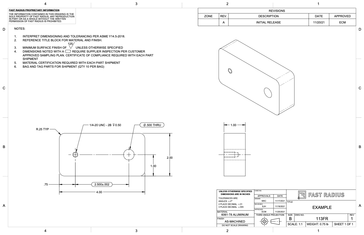
What to Include in Your Engineering Drawing Fast Radius
Engineering Drawings Justin R. Palmer

Mechanical Engineering Drawing and Design, Everything You Need To Know

Mechanical Engineer Drawing at GetDrawings Free download
Engineering Drawing at GetDrawings Free download
Lecture Notes Engineering Drawing Part 5
Creating Professional Technical Drawings With Autocad A Stepbystep
If The Isometric Drawing Can Show All Details And All Dimensions On One Drawing, It Is Ideal.
A Complete Understanding Of The Object Should Be Possible From The Drawing.
It's Designed For Beginners Who Are Eager To Explore This Fascinating World, As Well As For Professionals Who Wish To Refresh Their Knowledge.
It Is The Graphic Language From Which A Trained Person Can V Isualize Objects.
Related Post: